IECEx ATEX Certified Explosion proof LED Lights - Zone 1 Zone 2 Hazardous Area Lighting
CESP Zone 1 Zone 2 hazardous location LED lights are in accordance with International Protection Techniques (Equipment Protection Levels), including IEC/EN 60079-0 (General Requirement), IEC/EN 60079-1 (Flameproof Enclosure), IEC/EN 60079-7 (Increased Safety), IEC/EN 60079-11 (Intrinsic Safety), IEC/EN 60079-15 (Type of Protection), IEC/EN 60079-18, IEC/EN 60079-28, IEC/EN 60079-31. If you are not sure about the Classified of your lighting application environment, please contact our technical department for the solution.
For Zone 1 Zone 2, Zone 21 Zone 22 hazardous area led lighting, 20W - 200W, 130lm/W,aluminum alloy + 8mm tempered glass, multi-installation for different projects, such as light tower, canopy light, marine grade.
Flameproof enclosure, Ex db op is IIC T6 Gb, Zone 1 & Zone 21 with explosive gas atmosphere, Zone 21 and Zone22 with explosive dust atmosphere, 10mm temered glass, 7J impact resistance,up to 26000lm.
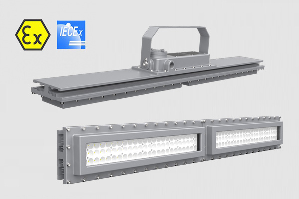
Flameproof enclosure, Ex db op is IIC T6 Gb, IP68 protection grade, tempered glass 10mm, withstand impacts up to 10J, 2 foot and 4 foot Length, 50Watt- 240Watt, 130lm/W light efficacy.
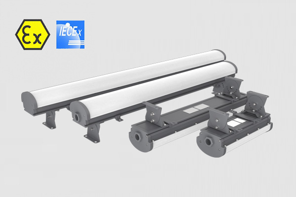
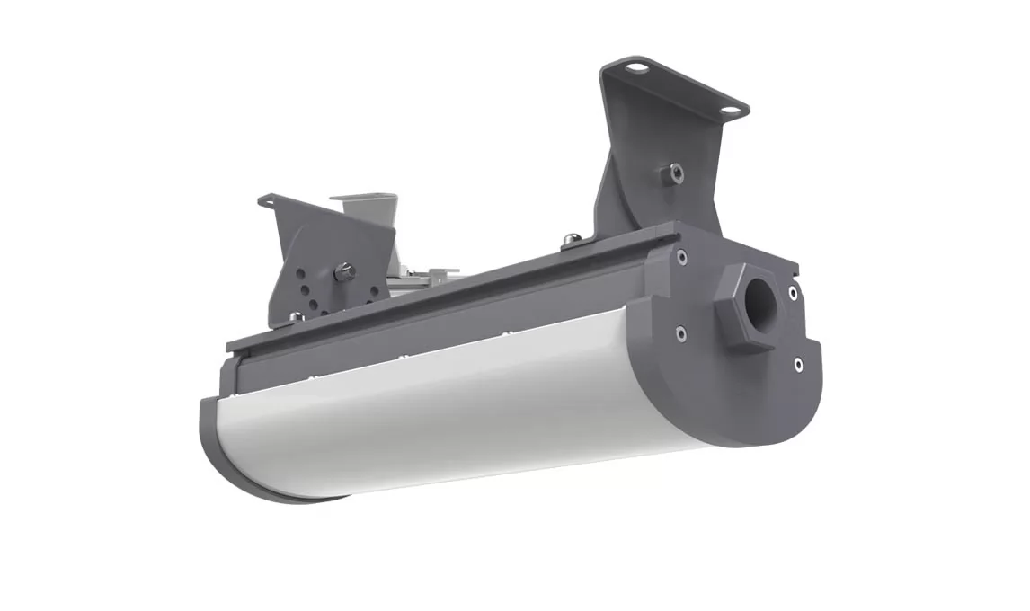
Zone 1 & Zone 21, 1ft, 2ft, 3ft, 4ft length can be selected, replace the traditional explosion-proof three-proof lamp, explosion-proof fluorescent tube, anti-corrosion, anti-glare, anti-drop, competitive price.
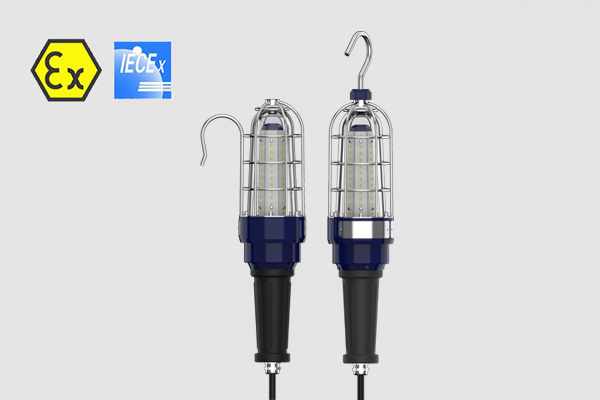
Flameproof LED hand lamp for Zone 1 & Zone 21 hazardous areas, 10mm tempered glass, pass the multi-angle drop test, 10W, 20W, 30W Power, can be connected to the cable, emergency power box.
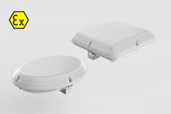
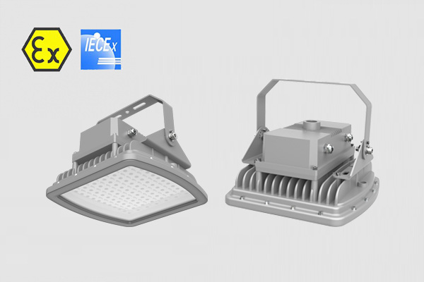
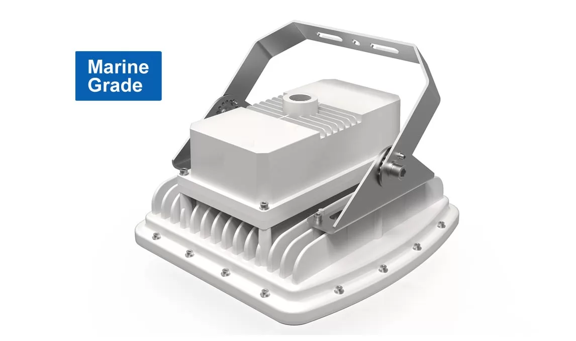
The CES-EX-SF series explosion-proof ceiling lamp has a strong shell, with features such as impact resistance, vibration resistance, and corrosion resistance. It can be used in hazardous environments of Zone 1&21, Zone 2&22.
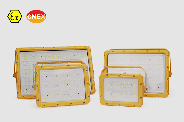
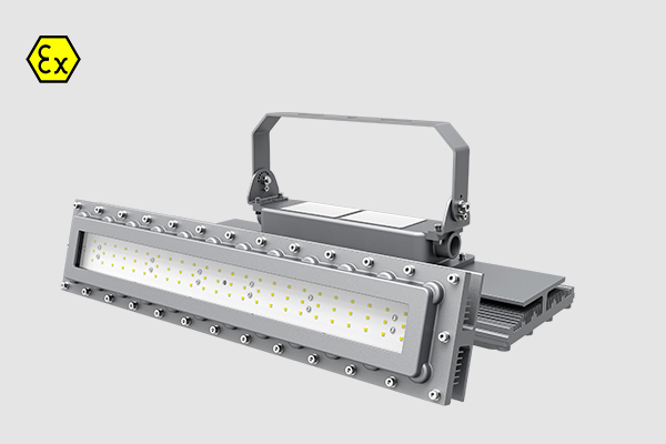
CES-EX-JX Series is your go-to solution for illuminating hazardous Zone 1 and Zone 21 areas. With ATEX approval, these Explosion-proof LED Flood Lights offer unbeatable safety standards.
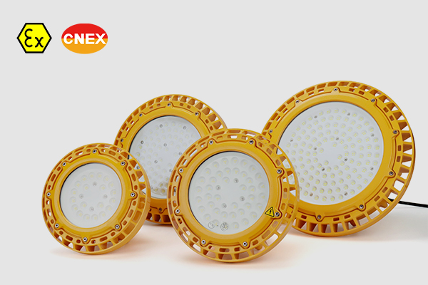
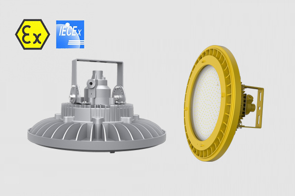
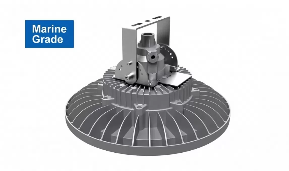
Discover the pinnacle of safety and illumination with our CES-EX-GBX Series Explosion-proof LED High Bay Lights. Designed for hazardous Zone 1 and Zone 21 areas, these lights boast ATEX approval, ensuring the highest safety standards.
GB-02 explosion-proof lights are made of alloy aluminum and tempered glass, with shock resistance and anti-vibration performance. The luminaires have passed the ATEX IECEx standards test, from 30W to 80W for hazardous area lighting.
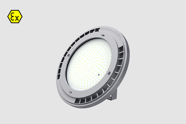
LN-02 explosion-proof lights obtained an IECEx ATEX certificate, it's safe for the Zone 1 and Zone 2 hazardous locations. The copper-free aluminum alloy body is powder-coated to increase durability and beautiful appearance, are able to withstand violent shaking and shock resistance.
an innovative line of LED hazardous area lighting products, specifically designed for use in potentially explosive atmospheres (Zone 1/21 & 2/22) within harsh industrial settings such as coal mines and oil & gas facilities.
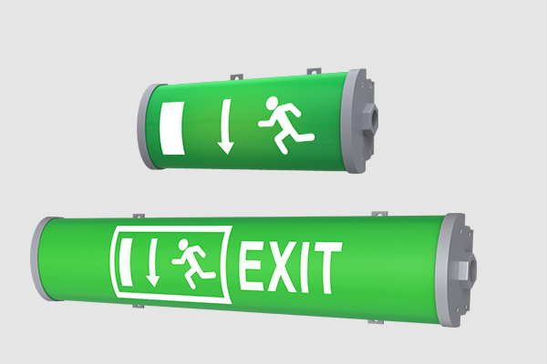
Explosion-proof safety exit lamps are for personnel evacuation, and fire operations to provide lighting fire emergency lamps! It usually uses an external power supply, when the power automatically switches to the battery power state!
Wednesday, 08 June 2022 08:37
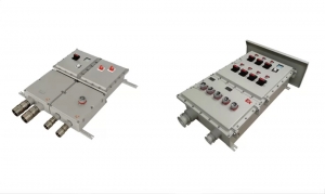
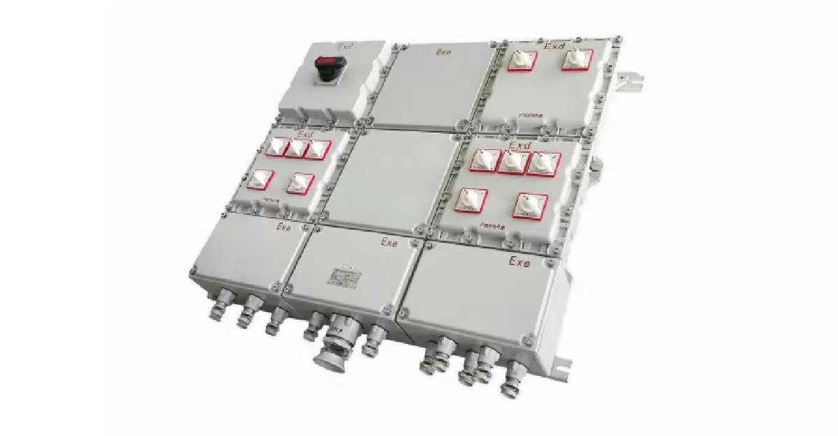
How to maintain explosion proof distribution panel and control station
Point. 1 Increase the emphasis on explosion proof distribution panel and control station
explosion proof distribution panel and control station are generally installed in places with harsh environments. They generally use cast iron casings. Chemical dust can chemically react with the cast iron casings, causing external corrosion or the formation of sticky attachments. Major damage, including mechanical jamming, aging plastic handlebars, corroded bolts, etc.
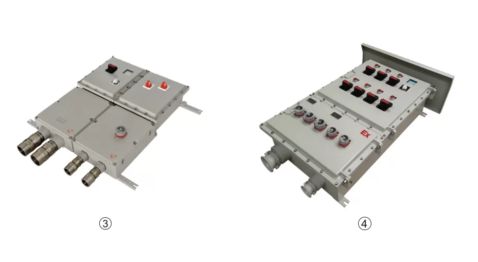
Explosion proof distribution panel and control station have to be updated in about 5 years. Some maintenance personnel are irresponsible, the explosion-proof end caps are not fixed well, and the terminal board is damaged at will, which will speed up its service life. Among them, the explosion proof distribution panel and control box start from the branch factory, strengthen their supervision and understand their importance. It cannot be regarded as just on-site equipment, which is maintained and managed by the chemical industry. explosion proof distribution panel are maintenance power supplies, not long-term or fixed equipment power supplies. Some maintenance power supplies have been occupied for a long time for water pumps, lighting or small equipment.
Point 2. Explosion proof distribution panel must be numbered uniformly
Many explosion proof distribution panel and control boxes have been uniformly numbered in the power distribution room, but the site number is confusing, and some signs have been dropped. , which greatly affects the maintenance efficiency. It is recommended that the low-voltage section use paint to mark the number at each explosion proof distribution panel and control panel to improve the identification and improve the maintenance efficiency.
Point 3. Adopt one-by-one contracting system
Number each explosion proof distribution panel and control station, and assign the operation section team to contract, and require the operation section on-duty to indicate the integrity of the explosion-proof control box in the work record when overhauling or using the explosion-proof distribution box and control box. And establish a registration book, fill in the registration book for each shift of the duty team, and report the missing bolts or broken end caps in time.
Point 4. Adopt the long-term maintenance system of sharding
The long-term maintenance system for explosion-proof distribution panel and control station is carried out by the team under the jurisdiction of the low-voltage section. Each explosion-proof distribution panel is registered and maintained, and the mechanical parts are maintained every month. Replacement, reinforcement of on-site signs and other related maintenance.
Point 5. Develop a long-term monitoring mechanism
A production period supervision mechanism is established for the explosion-proof control station, and one functional person in the operation section and the low-voltage section is assigned to check and register once a month, and the inspection content includes the identification.
1) Whether the bolts and end covers of explosion-proof distribution panel are in good condition;
2) Whether the explosion-proof distribution panel and control station are marked in the work record;
3) Whether the explosion-proof maintenance power supply is recorded in the contract registration form;
4) Whether the air switch and terminal board in the explosion-proof distribution panel and control station are in good condition; whether the wiring is firm, etc. And according to the relevant situation of the inspection, conduct a reasonable assessment of the operation section team and the low-voltage team.
Point 6. Other measures
1st. Improve the sleeve and hexagon socket tools to reduce the phenomenon that the explosion-proof control station cannot be removed or tightened due to tool defects.
2nd. Treat the bolts of the explosion-proof distribution box and control box, and use the welding and lengthening screws during installation to improve the maintenance efficiency of the operation section.
3rd. Try to use the same spare parts of the same type to reduce maintenance costs and improve maintenance efficiency.
Published in
CESP Ex Wiki
Saturday, 09 April 2022 07:40
Overview of ATEx and IECEx Certification
Equipment products certified by ATEX or IECEx are essential to be put into use in any potentially explosive or potentially explosive environments, and are an important guarantee to help create production safety. Most of us have heard of ATEX and IECEx certification, but many people sometimes still don't know the relationship between them. Let's introduce the relationship between the two certifications in detail.
IECEx explosion proof certification
International Electrotechnical Commission explosion-proof electrical product certification system (IEC Scheme for Certification to Standards for Electrical Equipment for Explosive atmospheres, hereinafter referred to as IECEx certification system) was established in 1996, is an international explosion-proof electrical product certification organization. Member countries of IECEx certification system include Australia, Canada, China, Denmark, Finland, France, Germany, Hungary, Italy, Japan, South Korea, Netherlands, Norway, New Zealand, Singapore, Romania, Serbia and Montenegro (formerly Yugoslavia), Russia, Slovenia , South Africa, Sweden, Switzerland, the United Kingdom and the United States 24, and are still increasing.
The goal of the IECEx system is to accept a standard worldwide ---- IEC/TC31 series of standards for electrical equipment for explosive hazardous environments; a certificate ---- IECEx certification certificate (IECEx Certification of Conformity); a mark -- -- IECEx certification mark (IECEx Mark of Conformity).
However, the explosion-proof products currently exported to EU countries only recognize the ATEX certificate, not the IECEx certificate. Some of the benefits of choosing a product with IECEx certification include:
(1) Increase market competitiveness. Products that have passed IECEx certification show that they have passed a series of tests of IEC60079 related standards and have reliable safety.
(2) Expand market circulation. At present, there are more than 50 member states of the IECEx system. Products used for IECEx certification can enter the market faster in these member states and shorten the time to market.
IECEx control products and main standards
The scope of IECEx controlled products is: pure electrical products/equipment used in explosion-proof environment, non-electrical products/equipment;
IECEx main standard: According to the difference in explosion-proof design of different equipment, it needs to be judged by professional and technical personnel. You can contact Eurotest for inquiries.
IECEx Certificate Overview
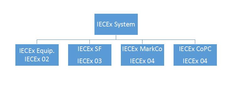
The IECEx certification system includes IECEx 02 product certification, IECEx 03 service certification, IECEx04 logo license, and IECEx05 personnel competency certification as shown in Figure as bellow,
IECEx Certificate System Component
IECEx Certificate System Component
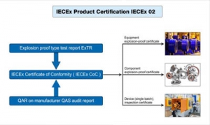
IECEx02 product certification stipulates that all explosion-proof products must meet the certification requirements. The certification process includes the applicant submitting the certification application, Ex TL conducting the explosion-proof type test, Ex CB conducting on-site inspection of the manufacturer's quality system, and Ex CB making the certification decision (issuing Ex TR and QAR), Ex CB issues the IECEx certification certificate, publishes it on the IECEx website, and Ex CB supervises the certified enterprise. Product certification is carried out in accordance with IECx OD003, IECEx OD009, IECEx OD017 and operation documents, and needs to meet the requirements of IEC 60079 series of technical standards. The quality system review of the manufacturer is carried out according to IEC OD005 operation documents. The simplified flow of certification procedures is shown in Figure

IECEx Certificate Flow Chart
IECEx03 service certification includes the audit of maintenance facilities, equipment and systems, confirmation of personnel's ability, and finally the generation of IECEx service certification. In order to meet the needs of the use department of Ex products for the quality certification of explosion-proof equipment repair and overhaul, the IECEx system began to launch IECEx service certification on the basis of explosion-proof product certification in 2003, including the factory or workshop certification plan for explosion-proof equipment repair and overhaul . In this regard, manufacturers of explosion-proof products can apply for IECEx service or choose to use manufacturers with IECEx system service certification.
The advantages of an explosion-proof product manufacturer applying for IECEx service include: it can prove the manufacturer's ability to repair explosion-proof products; if an explosion or fire occurs, it can resist liability lawsuits against the manufacturer for the repaired electrical equipment; it can ensure that explosion-proof products are in use consistency; enhances end-user confidence in purchasing products from explosion-proof product manufacturers. IECEx03 service certification is based on IECEx OD014 operation document, which puts forward specific requirements for the quality system, technical documents, facilities and equipment, and personnel of explosion-proof equipment repair factories; IECEx OD 013 operation document makes specific provisions for the review of Ex service certification; IEC60079 -19 made detailed requirements for specific content.
IECEx05 personnel competency certification provides proof that the knowledge and skills of personnel engaged in explosion-proof equipment and related personnel in explosive environments meet IECEx requirements, whether they have mastered safe operating procedures in hazardous locations, and whether they can correctly install, inspect, maintain and repair explosion-proof equipment and systems. . IECEx personnel competency assessment is carried out according to IECEx OD501, IECEx OD502, IECEx OD503, IECEx OD504 operation documents. The specific competency units are shown in Table 1. Each unit has clear requirements for personnel experience, knowledge and skills. Applicants need to have certain skills. Only after technical experience and training experience can you apply for evaluation. Unit 001 is the basic unit, and the unit must be based on 001 to apply for the evaluation of other units.
Table 1 Personnel competency certification components
|
No. |
Competency components |
|
1 |
Basic guidelines for applying explosion protection |
|
2 |
Zoning of hazardous locations |
|
3 |
Installation of explosion-proof equipment and wiring systems |
|
4 |
Maintenance of Explosive Atmosphere Equipment |
|
5 |
Overhaul and repair of explosion-proof equipment |
|
6 |
Testing of electrical installations related to explosive atmospheres |
|
7 |
Visual and general inspection of electrical installations in explosive atmospheres |
|
8 |
Detailed inspection of electrical installations in explosive atmospheres |
|
9 |
Design of Electrical Installations for Explosive Atmospheres |
|
10 |
Inspection of electrical installations in explosive atmospheres |
IECEx certification conducts international certification for explosion-proof electrical products in accordance with international standards, which can reduce the manufacturer's certification costs and time to enter the market on the premise of ensuring the appropriate safety level of explosion-proof electrical products, and maintain international standards in the process of product and service evaluation. And the service evaluation is included in an international database, which increases the user's trust in the manufacturer's or personnel's service, and has received extensive support from the industry and related parties in various countries.
Three main steps to obtain IECEx-COC explosion-proof certificate
- Obtaining IECEx-TR files;
- The factory has obtained the IECEx-QA explosion-proof system certificate;
- Register and record on IECEX official website to form IECEx-COC certificate.
Main classification of IECEx certificate
- Batch unit certification, that is, the IECEx certificate is only valid for this batch of products;
- COC type certification, that is, a specific type of product with a certain explosion-proof design meets the requirements of IECEx, and can be used for a long time under the condition that the IECEx system certificate is always valid;
- The IECEx explosion-proof system certificate is the QA certificate, which indicates that the certificate holder has the ability to control products that meet the requirements of the corresponding IECEx explosion-proof standards.
ATEX explosion-proof certification
The ATEX directive in CE certification is 2014/34/EU (the old directive 94/9/EC). ATEX is derived from the French "Atmosphere EXlposible". On March 23, 1994, the European Commission adopted "equipment and protection for potentially explosive environments. System" (94/9/EC) Directive. The Directive has been in use since 1996 and has been enforced since July 1, 2003.
This directive covers mine and non-mine equipment. Unlike previous directives, it includes mechanical equipment and electrical equipment, and extends the potentially explosive atmosphere to dust and flammable gases, flammable vapors and mists in the air. This directive is the "new approach" directive commonly referred to as ATEX 100A, the current ATEX explosion protection directive.
Manufacturers of equipment intended for use in potentially explosive atmospheres, applying the terms of the ATEX directive and affixing the CE mark, can sell their explosion-proof equipment anywhere in Europe without considering the application of additional requirements.
ATEX explosion-proof certification is a mandatory requirement for explosion-proof products to enter the EU market. Therefore, products used for explosive products entering the EU market must follow the ATEX directive, obtain ATEX certification, and affix the ATEX mark on the product.
|
Explosion-proof group classification |
|
|
Mining Group I |
Mining Group I |
|
Non-mining Group II |
Non-mining Group II |
|
Classification of explosion-proof areas |
|
|
Zone 0 (Gas) |
Areas where explosive atmospheres persist or occur frequently |
|
Zone 1 (Gas) |
When the equipment is in normal operation, the explosive environment exists or may exist for a long time, and the frequency is occasional |
|
Zone 2 (Gas) |
When the equipment is not operating normally, the explosive environment exists or may exist for a short period of time, and the frequency under normal circumstances is less likely to occur |
|
Zone 20 (dust) |
More than 1000 hours/year or more than 10%/cycle |
|
Zone 21 (dust) |
10~1000 hours/year or 0.1~10%/cycle |
|
Zone 22 (dust) |
Less than 10 hours/year or less than 0.1%/cycle |
Explosion-proof categories, zones and markings
|
ATEX |
|||
|
Standard |
EN60079 |
||
|
|
Group |
Areas |
Ex-Proof Marking |
|
Coal Mine |
I |
Category M1( I M 1 ) |
Ex ia I |
|
Ex Ib I |
|||
|
Ex d I |
|||
|
Category M2( I M 2 ) |
Manufacturer's certificate |
||
|
Gas-Ex |
II |
Zone 0 ( II 1 G ) |
Ex ia II C/B/A |
|
Ex s |
|||
|
Zone 1 ( II 2 G ) |
EEx ia II C/B/A |
||
|
EEx s |
|||
|
EEx ib II C/B/A |
|||
|
EEx d II C/B/A |
|||
|
EEx e |
|||
|
EEx px, py |
|||
|
EEx o |
|||
|
EEx q |
|||
|
EEx m |
|||
|
EEx s |
|||
|
|
|||
|
Zone 2 ( II 3 G ) |
Suitable for all types of zones 0 and 1 |
||
|
EEx nA |
|||
|
EEx nC |
|||
|
EEx nL |
|||
|
EEx nR |
|||
|
EEx pz |
|||
|
|
|||
|
Standard |
EN50281 |
||
|
Dust-Ex |
III |
Zone 20 ( II 1 D ) |
Ex 1D |
|
Zone 21 ( II 2 D ) |
Ex 2D |
||
|
Zone 22 ( II 3 D ) |
Ex 3D |
||
Explosive Hazardous Gas Classification
|
Group |
ATEX |
Typical gas |
Ignition characteristics |
|
I |
I |
Methane |
From easy to difficult |
|
II |
II A |
propane |
|
|
II B |
vinyl |
||
|
II C |
hydrogen |
||
|
Acetylene |
T-Class Classification
|
Temperature Classification |
safe surface temperature |
Common Explosive Gases |
|
T1 |
Less than or equal to 450 ℃ |
46 kinds of hydrogen, acrylonitrile, etc. |
|
T2 |
Less than or equal to 300 ℃ |
47 kinds of acetylene, ethylene, etc. |
|
T3 |
Less than or equal to 200 ℃ |
36 kinds of gasoline, crotonaldehyde, etc. |
|
T4 |
Less than or equal to 135 ℃ |
6 kinds of acetaldehyde, tetrafluoroethylene, etc. |
|
T5 |
less than or equal to 100 ℃ |
carbon disulfide |
|
T6 |
less than or equal to 85 ℃ |
Ethyl nitrate and ethyl nitrite |
Introduction of common explosion-proof methods
|
Explosion-proof way |
EN Standard |
Description of explosion-proof method |
|
Ex d - Flameproof |
EN 60079-1 |
When the equipment is in normal operation, the components that can generate the detonation source are put into the explosion-proof enclosure. The explosion-proof enclosure can withstand the internal explosion pressure without loss, and can effectively prevent the explosion from spreading to the outside of the enclosure. |
|
Ex e - Increased Safety |
EN 60079-7 |
Through the design of the product, the detonation source that can generate hot surface or arc or spark can be eliminated, so as to achieve the purpose of explosion protection. |
|
Ex i - Intrinsically Safe |
EN 60079-11 |
Circuit energy is limited by related techniques so that sparks or hot surfaces from electrical energy in electrical equipment are not sufficient to detonate substances in explosive atmospheres. |
|
Ex m - Encapsulation |
EN 60079-18 |
The equipment or its part that may ignite the substances in the explosive atmosphere is sealed in a substance, and the equipment or its part is isolated from the substances in the explosive atmosphere, so as to achieve the purpose of explosion protection. |
|
Ex n - non-sparking |
EN 60079-15 |
The magic seal is used to prevent the flammable substances in the explosive environment from contacting the sparks or arcs generated by the equipment, and at the same time eliminate the hot surface generated by the equipment, so as to achieve the purpose of explosion-proof. |
|
Ex p - Pressurized Enclosure |
EN 60079-2 |
The equipment or components that will generate the detonation source are prevented from being contained in an enclosure. The enclosure is first filled with an inert gas to remove the flammable substances in it, and at the same time, by maintaining the pressure inside the enclosure, the entry of external flammable substances is prevented, thereby preventing the entry of flammable substances. To achieve the purpose of explosion-proof. |
|
Ex o - Oil Immersion |
EN 60079-6 |
Submerge the entire components of electrical equipment in a protective liquid so that substances in the explosive atmosphere cannot contact the hot surfaces or sparks of the equipment. |
|
Ex q - Powder Filling |
EN 60079-5 |
Bury the components of electrical equipment in sand so that substances in the explosive atmosphere cannot relieve hot surfaces or sparks of the equipment. |
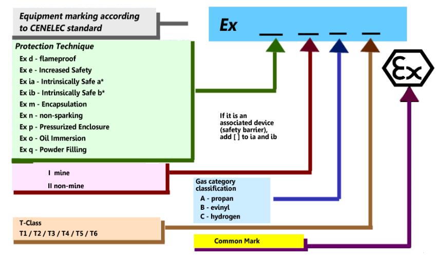
ATEX Explosion-proof Marking(for reference only)
The main difference between ATEX certification and IECEx certification
Although both ATEX certification and IECEx certification describe the necessary requirements for equipment used in potentially hazardous and hazardous locations, they differ in some respects, the main difference being that ATEX certification is driven by laws and IECEx certification is driven by standards.
Another difference is that ATEX certification is only valid in the EU, while IECEx certification is accepted worldwide. Likewise, ATEX certification is required by law for all non-electrical and electrical equipment to be used in hazardous locations. However, IECEx certification is only required for electrical equipment in hazardous locations.
In terms of standards, it is not mandatory for ATEX certification to conform to the standard, but for IECEx certification, a third-party certification body is responsible for combining all aspects of manufacturing and design for public certification. In short, IECEx certification is stricter than ATEX certification in the handling of evidence during the certification process.
Another fundamental difference is how each guide is set up. The IECEx certification system is actually one of the four conformity assessment systems operated by the IEC. The IECEx certification system consists of four independent international certification parts, including the IECEx Certified Equipment Program, the IECEx Certified Service Program, the IECEx Certified Conformity Mark Licensing System and the IECEx Certified Qualified Persons Program. However, ATEX certification refers to two separate but related directives, as described above.
The following list illustrates the relationship
|
Content |
ATEX |
IECEx |
|
Scope of application |
European |
IECEx member countries (except North American countries) |
|
Is it mandatory |
Mandatory |
Non-Mandatory |
|
Executive standard |
IEC60079 |
IEC60079 |
|
Explosion-proof mark |
|
Printed Ex logo |
|
convert |
At present, ATEX certificates cannot be converted into certificates from other countries outside the EU |
IEC member countries (except North American countries) recognize the IECEx report, which can be directly converted into the explosion-proof certification of the local country, except that some countries need to do some local difference tests. |

Published in
CESP Ex Wiki
Thursday, 24 March 2022 09:35
Lighting Requirements for Offshore Drilling Rig Platforms
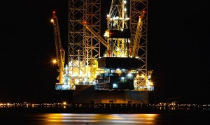
The lighting system is one of the branches of the power system of the offshore platform, which is directly related to the safety production of the platform and the quality of life of the staff. This paper briefly introduces the selection, installation method, lighting arrangement, system power supply requirements and control of the lighting system of the offshore platform.
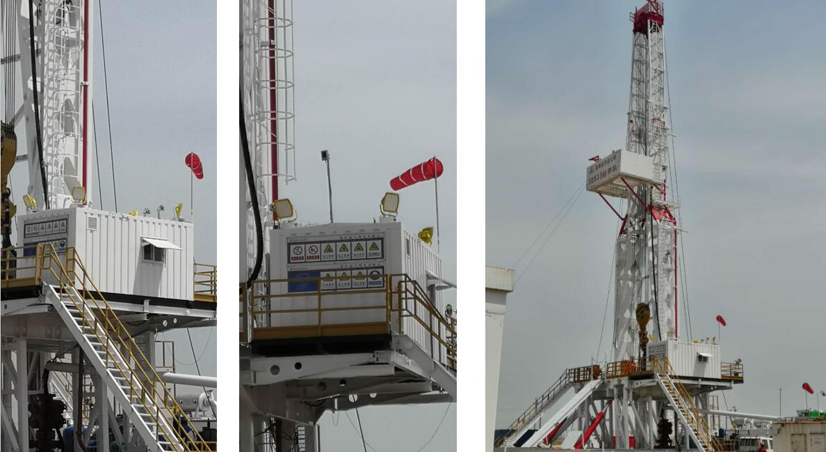
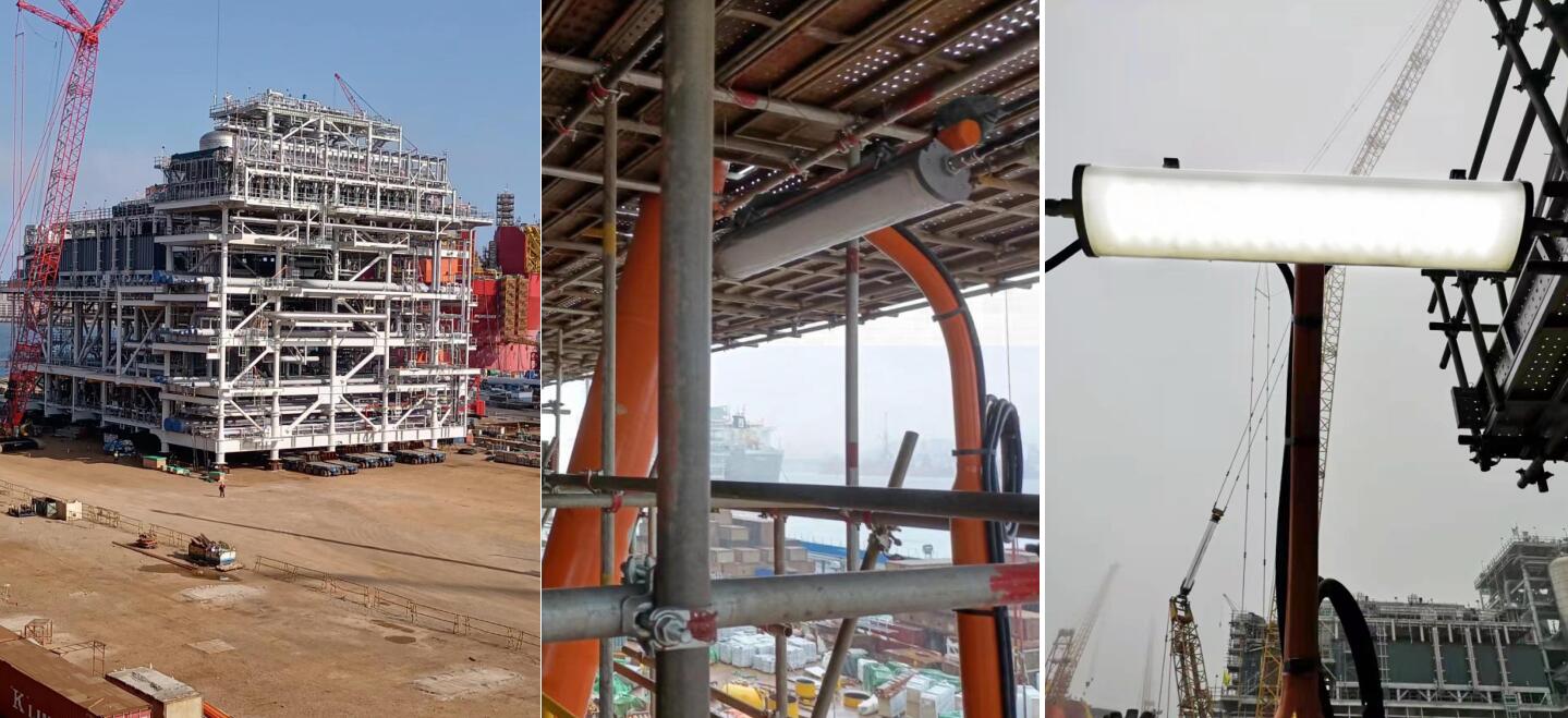
CESP LED Explosion proof Lights for Drilling Platform
Part.1 How to select lighting fixtures for offshore platform
The protection level and explosion-proof level of the lamp housing shall be suitable for the installation site and shall meet the following requirements:
The minimum requirements for the protection level of indoor dry spaces should meet IP23;
- The minimum requirements for indoor large dripping spaces and mechanical damage hazard spaces shall meet IP34;
- The minimum requirements for ballast pump rooms, refrigerated rooms, galleys and laundry rooms should meet IP44;
- The minimum protection level for outdoor and open decks should meet IP55.
- When it is in the open air or exposed to rain and waves, the minimum protection level should meet IP56.
Positive pressure ventilation (Exp), flameproof (Ex d) and intrinsically safe (Ex "ia" or "ib") are available in Class 1 hazardous areas. Increased safety (Ex e), positive pressure ventilation (Exp), flameproof (Ex d) and intrinsically safe (Ex "ia" or "ib") are available in Class 2 hazardous areas.
Some marine lighting fixtures and explosion proof lights from CESP for you reference. or you can send the project requirement to us directly.
Part. 2 The type of lighting fixtures and installation
The types of lighting fixtures for offshore platforms can be divided into: fluorescent lamps, high pressure sodium lamps, metal halide lamps, emergency exit lamps, aircraft deck boundary lamps, windsock lamps, etc. Each type of lamps is used in different locations. The following mainly introduces fluorescent lamps and high pressure sodium lamps. , the installation of emergency exit lights.
- Fluorescent lamps: embedded, pole-mounted, wall-mounted, ceiling-mounted, etc.; embedded spaces are used for indoor spaces with ceilings. The pole-mounted type is installed on the boundary of the platform, the wall-mounted type is installed on the firewall, and the hoisting type is installed in the indoor mechanical space.
- High pressure sodium lamp: The high pressure sodium lamp on the platform is divided into flood light and flood light. The flood light is installed on the platform column with a height of 5.5~6 meters. The flood light mainly illuminates the interior of the platform. The floodlight should ensure that its movable part is within the illumination range required by the work, and the rotation is flexible and unobstructed, and the light is not obstructed. Flood lights are also installed on the border of the platform, mainly illuminating the sea surface.
- The emergency exit light is the light fixture of the emergency lighting system. Installed at the door of the room, it is used to indicate the escape route and indicate the rapid evacuation of personnel.
Part.3 Illumination requirements for lighting fixtures
The number and location of lamps in each area depends on the average illuminance of the room. Different areas and rooms have different illuminance requirements. The average illuminance of each area on the platform is as follows:
|
Area |
Normal lighting (average illuminance) |
|
Staircase/passage area |
100 Lux |
|
Restrooms/toilets/changing rooms/other areas |
100 Lux |
|
material storage area |
100 Lux |
|
occupancy cabin |
150 Lux |
|
machinery spaces |
150 Lux |
|
Dining Room/Infirmary/Office/Control Room/Telegraph Room |
200 Lux |
|
kitchen |
300 Lux |
|
Frequency conversion room/electrician room/distribution room |
300 Lux |
Part.4 The layout of lighting fixtures
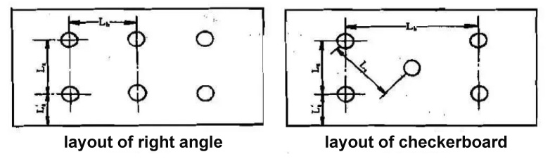
On the basis of the selected lighting fixture model, power and quantity, the cabin lighting fixtures can be arranged. While arranging, the environmental conditions of the cabin should be fully considered, and the main body should be illuminated evenly if possible. Due to the limited space in the cabin, in addition to lighting fixtures, there may be air conditioning vents, fire detectors, speakers, etc. on the ceiling. Therefore, the arrangement of lamps and lanterns must be carefully coordinated with the relevant professions. Make the lighting reasonable, beautiful and applicable as much as possible. When there is only one light in the cabin, it is generally arranged in the center, or close to the working position, and avoid placing it above the bed or in a position that may be severely blocked; when there are two or more lights in the cabin, it is In order to make the lighting of the whole room uniform, and considering the appearance of the cabin, the layout is often symmetrical. The arrangement of multiple lamps can be arranged in a right-angle or checkerboard arrangement as shown in the following figure:
The layout of other areas of the platform lighting fixtures should pay attention to the following aspects:
- It should be ensured that there is sufficient lighting in places where frequent operations and maintenance are required.
- The escape route, emergency escape and fire fighting equipment and other premises must have emergency temporary lighting.
- The arrangement and installation position and height of the lamps should ensure that the lamps are easy to operate and maintain, avoid being arranged above the movable equipment, and do not affect the aisles and safety passages, and provide lighting for the platform to the maximum extent; lamps should not be arranged in the pipeline method. To avoid the gasket breaking and the medium in the pipe spraying to the lamp.
- Emergency lighting should be arranged in the emergency equipment area so that the operation and maintenance of emergency equipment will not be affected when the emergency generator supplies power.
- The light of the lamp is not affected by any obstacles.
- The aircraft deck boundary lights and windsock lights shall ensure the safe take-off and landing of the helicopter on the offshore platform, and the arrangement and installation position shall comply with the relevant.
CESP Case: CNOOC - Oilfield & Offshore Lighting Engineering Project
Part.5 Lighting system power supply and control
Lighting can be divided into: normal lighting system, emergency lighting system, temporary emergency lighting system. The normal lighting switchboard shall not be placed in the same space as the emergency lighting switchboard. Except for personnel living spaces, the emergency light points in other spaces of the platform should be higher than at least 1/3 of the total number of light points in the room. Each lighting circuit shall be provided with overload and short circuit protection. Each lighting switchboard with a capacity greater than 16A should have no more than one last shunt power supply lamp.
The number of points of the last shunt-supplied lamps with a capacity less than or equal to 16A shall not exceed:
For circuits of 50V and below: 10 points
For 51~120V circuit: 14 points
For 121~250V circuit: 24 points
The power supply lamp head is close to the final shunt of the clustered cornice lighting, wall lamps, electric signs, etc. If the maximum working current does not exceed 10A, the lamp points supplied can be unlimited. The last branch of the lighting circuit should not supply power to electric heating and electrical equipment, but for small kitchen equipment (such as bread toasters, small mixers, coffee pots), small electric motors (such as desk fans, cabin fans, refrigerators) ), wardrobe heaters and the like may be excluded. For large machinery spaces, large galleys, passages (including entrances and exits), stairways leading to lifeboat decks and public spaces, the lighting is to be powered by at least two final branches for lighting. When any one of the routes is not powered, the other route should still be able to maintain the above necessary lighting.
The lighting system of the offshore platform directly affects the overall quality of the platform, so the lighting design must not only be meticulous, but also pay attention to methods, make overall arrangements, and follow specifications.
Published in
CESP Ex Wiki
Friday, 18 March 2022 05:35
AQ 1043-2007 Mining Product Safety Signs
1 Scope
This standard specifies the requirements for the classification, type, size, material, color, use and management of safety signs for mining products.
This standard applies to mining products that have been included in the management of safety signs and have obtained safety signs.
2 Terms and Definitions
The following terms and definitions apply to this standard.
2.1 Mining Products
The general term for equipment, materials, and instruments used in mines.
2.2 Mining Products Safety Label
Graphical and numerical codes for safety signs for mining products.
3 General requirements
3.1 The mining product safety sign management system is a mandatory management system for mining products involving workplace safety and worker health. All mining products included in the safety sign management can only be obtained after obtaining the mining product safety sign. production, sale and use.
3.2 The safety mark of mining products is a certificate that confirms that the mining products conform to national standards and industry standards, that production units are permitted to produce and sell, and that users purchase and use them.
3.3 The mining product safety sign consists of two parts: the mining product safety sign certificate and the mining product safety sign.
3.4 Mining product safety signs and logos (hereinafter referred to as "logos") are special signs that indicate that mining products comply with national standards, industry standards and relevant regulations on mine safety production.
For the production of mining products that are included in the management of safety signs, the signs can only be used after obtaining the safety signs of mining products.
3.5 Products that have obtained safety signs for mining products can only be sold by the production unit after the label is applied, and purchased and used by the user unit.
4 Identification Types
The identification is divided into safety signs for coal mine products and safety signs for metal and non-metal mine products, and there are standard and non-standard types.
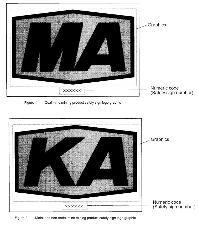
4.1 Coal mine product safety signs
The standard identification is a hexagonal frame with the Chinese Pinyin abbreviation "MA", which means "coal safety". The frame line indicates that the scope of coal mines in the country is applicable, and the digital code is the safety sign number, as shown in Figure 1.
4.2 Safety signs for metal and non-metal mine products
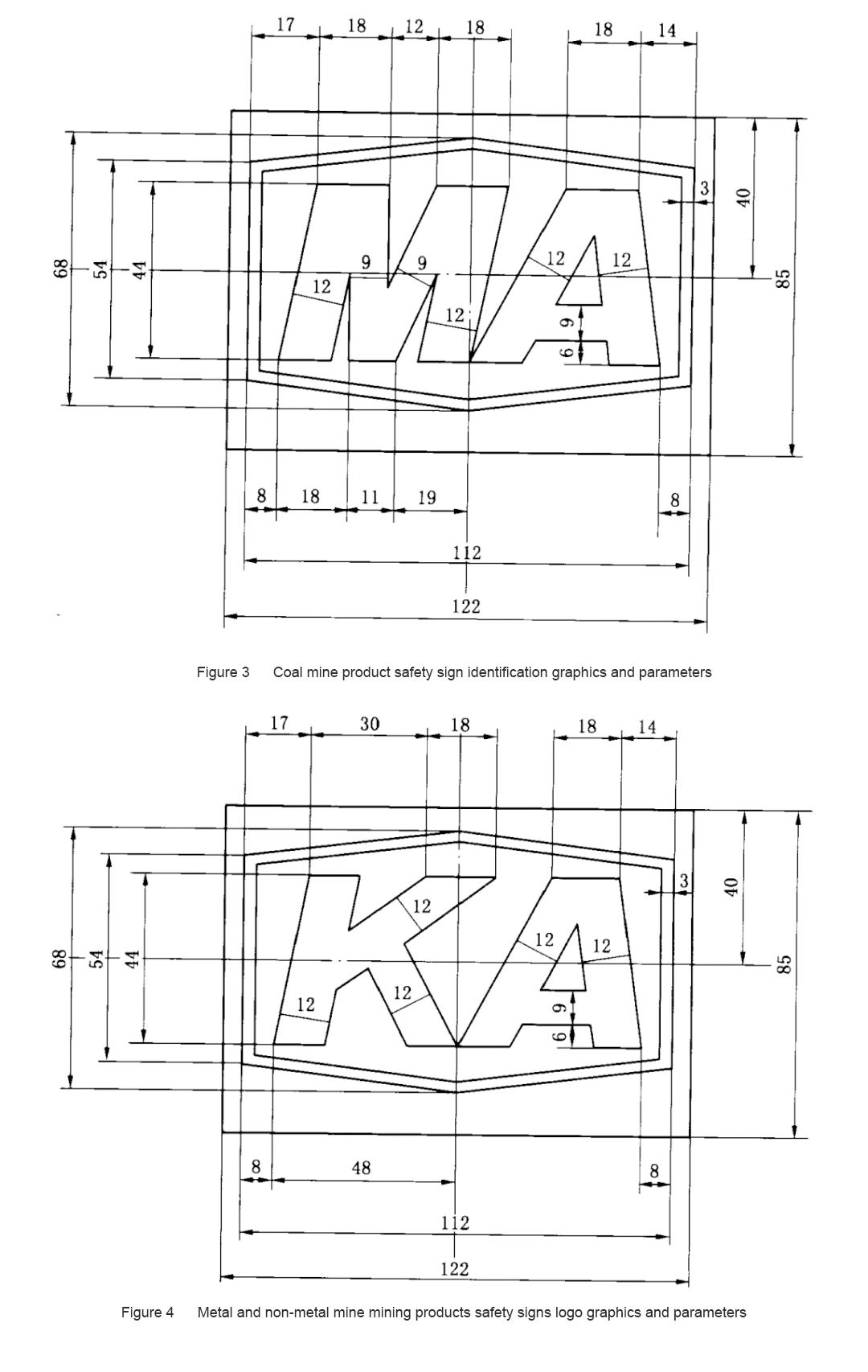
The standard identification is a hexagonal frame with the Chinese Pinyin abbreviation "KA", meaning "mine safety", the frame line indicates the scope of the national metal and non-metallic mines, and the digital code is the safety sign number, as shown in Figure 2.
5 Identification graphics and parameters
5.1 Standard identification
5.1.1 The standard logo graphics and parameters are shown in Figure 3 and Figure 4.
5.1.2 There are five specifications for the standard type identification, and the ratio of each specification size to the marked size in Figure 3 or Figure 4 is shown in Table 1.
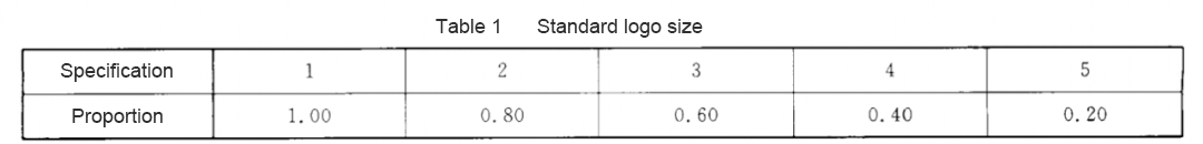
5.1.3 The digital code (safety sign number) is marked below the hexagonal frame, at the center of the sign.
5.1.4 The standard logo is a yellow base plate, and the frame and "MA" and "KA" are black.
5.2 Non-standard identification
When it is inconvenient to use standard logos, non-standard logos can be applied to products by means of printing, molding, branding, etc. The position of the digital code, graphic size, color and whether to use a hexagonal frame can be determined according to specific circumstances.
6 Identify other requirements
6.1 Marking material
Standard signs should be made of materials permitted by mine safety, generally brass or stainless steel.
6.2 Identifying the surface quality
The identification should be clear and free of burrs.
7 Use of the logo
7.1 The logo should be applied to the obvious position of the outer body of the product, and the selected specifications should be compatible with the overall dimensions of the product.
7.2 For cables, conveyor belts, pipes, air ducts (cloth) and other products, the distance between the markings shall not be greater than 10 m, and there shall be no less than one marking in the minimum use unit of the product.
7.3 If the logo cannot be applied on the product body, the logo should be applied on the smallest package of the product.
7.4 Mining products that have obtained safety signs shall be marked before leaving the factory; imported mining products that have obtained safety signs in batches shall be marked before the products are delivered for use.
8 Management of logos
8.1 The labels shall be uniformly managed by the state-authorized mining product safety label review and issuance agencies.
8.2 For non-standard signs, the production unit that has obtained the safety sign shall apply to the state-authorized mining product safety sign review and issuance agency, and can only be used after confirmation and filing.
8.3 Mining products managed by Vanner Safety Signs shall not use the signs without obtaining the safety signs of mining products.
Published in
CESP Ex Wiki