
Thursday, 07 April 2022 01:58
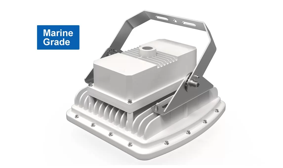
Explosion Proof Emergency Lighting - 1.5 Hours - 60W/80W/100W
Description:
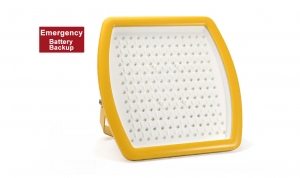
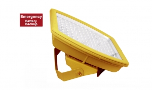
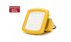
This explosion proof emergency flood light fixtures with an emergency backup battery (12W Li-ion battery), the emergency backup lighting provide 1680 lumens for the 1.5 hours. For the normal lighting , the input voltage is AC100 - 277V, 60W, 80W, 100W power optional.
For design and structure, this emergency explosion proof light made of the die-cast aluminum and the 8mm high tempered glass. Good heat and 6J impact resistance.
If you need anti-corrosion performance for the marine environment, that is optional. We adopt to the electrophoresis technology and the multiple coats of marine anti-corrosion paint, the all the mounting brackets and accessories are made of 316 stainless steel. Certified by UL1598A and CCS.
Design standard of CES-J: EN 60079-0: 2013 ; EN 60079-7: 2015 ; EN 60079-18: 2015 ; EN 60079-28: 2015 ; EN 60079-31:2014;
Warning:
- “WARNING – DO NOT OPEN WHEN ENERGIZED”
- “WARNING – DO NOT OPEN WHEN AN EXPLOSIVE ATMOSPHERE IS PRESENT”
- “WARNING – ONLY USE CABLES SUITABLE FOR 85°C”
- End user shall use certified cable gland or conduit with suitable type of protection for final installation purpose.
- External earthing wire shall be connected when used and the cross-sectional areashall be more than 4mm2 or 10AWG.
- Under rating condition, maximum temperature on the luminaire’s shell shall not be higher than 95℃ for T4.Temperature at cable inlet shall not be higher than allowable limit of the cable applied, to ensure the cable operation normally.
Features
- Industry-leading efficacy: up to 130lm/W±5
- -40°C to +55°C Ambient operating temperature
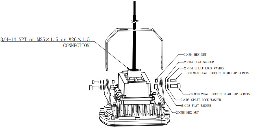
- Amounting: U-bracket
- Wide optics for uniform illumination
- 5 years warranty
- Entry Size: M25Χ1.5 or NPT 3/4”-14
- Housing –Aluminum alloy (ADC12 )
- Lens – tempered glass
- Beam angle: 8°, 15°, 35°, 60°, 90°, 108°, 120°
Parameters
- Power:60W/80W/100W
- Input voltage: AC100-240/277V, 50/60Hz
- Power factor: 0.97
- Lumen flux: 7200lm / 9600lm / 12000lm
- CCT: 2700K - 6500K (Optional)
- LEDs: 3030
- LED Driver: Meanwell HLG series
- Dimension: 300mm x300mm x 165(251)mm
- Weight: 7.5KG
- Backup battery: Li-ion battery, 12W power
- Emergency: ≥90 mins
Certificate & Standard
Have certified CES-J light fixtures with the IECEX and ATEX standards for hazardous location and environments.
ATEX:
- EX II 2G Ex eb mb op is IIC T4 Gb
- EX II 2D Ex op is tb IIIC T95°C Db
- IP66
- Certify No:IEP 19ATEX 0714
IECEx:
- Ex ec IIC T4 Gc
- IP66
- Certify No:IECEx UL 18.0046
Special order
- Special Orders- Requirements
Contact us for special requirements
Tel: +86-755-83509822
Fax: +86-755-83509868
Email: This email address is being protected from spambots. You need JavaScript enabled to view it.
Email: This email address is being protected from spambots. You need JavaScript enabled to view it.
Published in
Explosion proof LED Flood Light
Tagged under
Wednesday, 06 April 2022 08:34
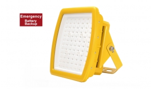
Explosion Proof Emergency Lighting - 1.5Hours - 20W/30W/40W
Description:
This explosion proof emergency flood light fixtures with an emergency backup battery (12W Li-ion battery), the emergency backup lighting provide 1680 lumens for the 1.5 hours. For the normal lighting , the input voltage is AC100 - 277V, 20W, 30W, 40W power optional.
If you need anti-corrosion performance for the marine environment, that is optional. We adopt to the electrophoresis technology and the multiple coats of marine anti-corrosion paint, the all the mounting brackets and accessories are made of 316 stainless steel. Certified by UL1598A and CCS.
• Applies to hazardous locations of Zone 1 and Zone2 with explosive gas atmosphere.
• Applies to hazardous locations of Zone 21 and Zone22 with explosive dust atmosphere.
Design standards: EN 60079-0: 2013 ; EN 60079-7: 2015 ; EN 60079-18: 2015 ; EN 60079-28: 2015 ; EN 60079-31:2014;
Warning:
- “WARNING – DO NOT OPEN WHEN ENERGIZED”
- “WARNING – DO NOT OPEN WHEN AN EXPLOSIVE ATMOSPHERE IS PRESENT”
- “WARNING – ONLY USE CABLES SUITABLE FOR 85°C”
- End user shall use certified cable gland or conduit with suitable type of protection for final installation purpose.
- External earthing wire shall be connected when used and the cross-sectional areashall be more than 4mm2 or 10AWG.
- Under rating condition, maximum temperature on the luminaire’s shell shall not be higher than 95℃ for T4.Temperature at cable inlet shall not be higher than allowable limit of the cable applied, to ensure the cable operation normally.
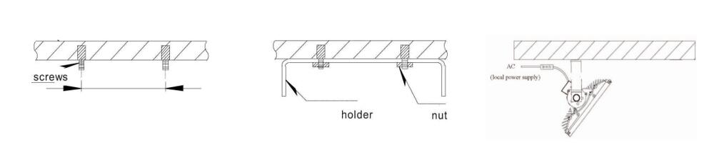
Mounting:
Fix 2 M10 screws on the wall according to the distance between the holes of the bracket. Install the bracket on the screws and then fasten it with the nut. Fix the position of the lamp Place the lamp cord into the pole; connect the wire to local power supply (AC100-277V).
Features
- Industry-leading efficacy: up to 140lm/W
- -40°C to +55°C Ambient operating temperature
- Amounting: U-bracket
- Wide optics for uniform illumination
- 5 years warranty
- Entry Size: M25Χ1.5 or NPT 3/4”-14
- Housing –Aluminum alloy (ADC12 )
- Lens – tempered glass
- Beam angle: 8°, 15°, 35°, 60°, 90°, 108°, 120°
Parameters
- Power:20W / 30W / 40W
- Input voltage: AC100-240/277V, 50/60Hz
- Power factor: 0.97
- Lumen flux: 2400lm / 3600lm / 4800lm
- CCT: 2700K - 6500K (Optional)
- LEDs: 3030
- LED Driver: Meanwell HLG series
- Dimension: 200mm*200mm*147mm
- Weight: 4KG
- Backup battery: Li-ion battery, 12W power
- Emergency: ≥90 mins
Certificate & Standard
Have certified CES-J fixtures with the IECEX and ATEX standards for hazardous location and environments.
ATEX:
- EX II 2G Ex eb mb op is IIC T4 Gb
- EX II 2D Ex op is tb IIIC T95°C Db
- IP66
- Certify No.:IEP 19ATEX 0714
IECEx:
- Ex ec IIC T4 Gc
- IP66
- Certify No:IECEx UL 18.0046
Special order
- Contact us for special requirements
Tel: +86-755-83509822
Fax: +86-755-83509868
Email: This email address is being protected from spambots. You need JavaScript enabled to view it.
Email: This email address is being protected from spambots. You need JavaScript enabled to view it.
Published in
Explosion proof LED Flood Light
Tagged under
Wednesday, 06 April 2022 06:58
Explosion Proof Emergency Light 1.5 Hours - Class 1 Division 2 - 120W/150W/185W
Features:
CES-J120/J150/185 hazardous location emergency light fixtures with an emergency backup battery that provides energy-efficient illumination, the emergency backup provides 1680 lumens for 1.5 hours. For normal lighting, the input voltage is AC100 - 277V, 120W, 150W, 185W power optional, up to 25900-lumen flux. These floodlight hazardous location LED fixtures only obtained UL844, and can use for Class 1 Div 2, Groups A, B, C, and D. For design and structure, these emergency hazardous location LED fixtures are made of die-cast aluminum, and the 8mm high tempered glass. Good heat, and 6J impact resistance.
If you need anti-corrosion performance for the marine environment, that is optional. We adapt to the electrophoresis technology and multiple coats of marine anti-corrosion paint, all the mounting brackets and accessories are made of 316 stainless steel.
Warning:
CUL for Hazloc:
- SUITABLE FOR WET LOCATIONS;
- THIS LUMINAIRE IS ACCEPTABLE FOR OPERATION IN AMBIENT CONDITIONS NOT EXCEEDING 40°C;
- FOR SUPPLY CONNECTION, USE WIRES RATED FOR AT LEAST90°C;
- NO SERVICEABLE PARTS” OR “NO USER SERVICEABLE PARTS. DO NOT OPEN FOR CLEANING.;
- CAUTION - ″TO REDUCE THE RISK OF IGNITION OF HAZARDOUS ATMOSPHERES, DISCONNECT THE LUMINAIRE FROM THE SUPPLY CIRCUIT BEFORE OPENING. KEEP TIGHTLY CLOSED WHEN IN OPERATION.″;
- THIS PRODUCT MUST BE INSTALLED IN ACCORDANCE WITH THE APPLICABLE INSTALLATION CODE BY A PERSON FAMILIAR WITH THE CONSTRUCTION AND OPERATION OF THE PRODUCT AND THE HAZARDS INVOLVED;
- “CAUTION – RISK OF SHOCK” and “DISCONNECT POWER BEFORE SERVICING”.
UL for marine locations:
- OUTSIDE TYPE or OUTSIDE TYPE (SALT WATER);
Features
- Industry-leading efficacy: up to 140 lm/W
- -40°C to +55°C Ambient operating temperature
- Wide optics for uniform illumination
- Entry Size: NPT 3/4”-14 ;
- Housing –Aluminum alloy (ADC12 );
- Lens –tempered glass
- Beam angle: 108°, 120°
- Dimension: 400x400x169mm
- Weight: 10.5kg
Parameters
- Power: 120W/ 150W / 185W
- Input voltage: AC100-240/277V, 50/60Hz
- Power factor: 0.97
- Light efficacy: 120 - 140lm/W
- CCT: 3000K/4000K/5000K/5700K/6500K
- LEDs: 3030
- LED Driver: Meanwell HLG series
- Backup battery: Li-ion battery, 12W power
- Emergency: ≥90 mins
Certificate & Standard
Have certified CES-J fixtures with the NEC and CEC standards for hazardous location and environments
- Class I, Division 2, Groups A, B, C and D
- T-Class: T5
- Damp and wet locations
- Certificate No:E475887
- US: UL 844; UL 1598A;
- Canada: CSA C22.2 No. 137; CSA C22.2 No. 250.0;
Mounting
Versatile mounting options:
- Ceiling mount
- Drop mount
- Pole mount
- Wall Mount
- Mounting Angle:0°to ±90°;
Published in
Hazardous Locaiton LED Flood Light
Tagged under
Wednesday, 06 April 2022 06:58
Explosion Proof Emergency Light 1.5 Hours - Class 1 Division 2 - 60W/80W/100W
Features:
CES-J SERIES hazardous location emergency light fixtures with an emergency backup battery that provides energy-efficient illumination, the emergency backup provides 1680 lumens for 1.5 hours. For normal lighting, the input voltage is AC100 - 277V, 60W, 80W, 100W power optional, up to 14000-lumen flux.
These floodlight hazardous location LED fixtures only obtained UL844, and can use for Class 1 Div 2, Groups A, B, C, and D. For design and structure, these emergency hazardous location LED fixtures are made of die-cast aluminum, and the 8mm high tempered glass. Good heat, and 6J impact resistance.
If you need anti-corrosion performance for the marine environment, that is optional. We adapt to the electrophoresis technology and the multiple coats of marine anti-corrosion paint, all the mounting brackets and accessories are made of 316 stainless steel.
Warning:
CUL for Hazloc:
- SUITABLE FOR WET LOCATIONS;
- THIS LUMINAIRE IS ACCEPTABLE FOR OPERATION IN AMBIENT CONDITIONS NOT EXCEEDING 40°C;
- FOR SUPPLY CONNECTION, USE WIRES RATED FOR AT LEAST90°C;
- NO SERVICEABLE PARTS” OR “NO USER SERVICEABLE PARTS. DO NOT OPEN FOR CLEANING.;
- CAUTION - ″TO REDUCE THE RISK OF IGNITION OF HAZARDOUS ATMOSPHERES, DISCONNECT THE LUMINAIRE FROM THE SUPPLY CIRCUIT BEFORE OPENING. KEEP TIGHTLY CLOSED WHEN IN OPERATION.″;
- THIS PRODUCT MUST BE INSTALLED IN ACCORDANCE WITH THE APPLICABLE INSTALLATION CODE BY A PERSON FAMILIAR WITH THE CONSTRUCTION AND OPERATION OF THE PRODUCT AND THE HAZARDS INVOLVED;
- “CAUTION – RISK OF SHOCK” and “DISCONNECT POWER BEFORE SERVICING”.
UL for marine locations:
- OUTSIDE TYPE or OUTSIDE TYPE (SALT WATER);
Features
- Industry-leading efficacy: up to 140lm/W
- -40°C to +55°C Ambient operating temperature
- Wide optics for uniform illumination
- Fixture warranty
- Entry Size: NPT 3/4”-14 ;
- Housing –Aluminum alloy (ADC12 );
- Lens –tempered glass
- Beam angle: 108°, 120°
- Dimension: 300x300x165mm
- Weight: 7.5kg
Parameters
- Power: 60W / 80W / 100W
- Input voltage: AC100 - 277V, 50/60Hz
- Power factor: 0.97
- Light efficacy: 110 - 140lm/W
- CCT: 3000K/4000K/5000K/5700K/6500K
- LEDs: 3030
- LED Driver: Meanwell HLG series
- Backup battery: Li-ion battery, 12W power
- Emergency: ≥90min
Certificate & Standard
Have certified CES-J fixtures with the NEC and CEC standards for hazardous location and environments
- Class I, Division 2, Groups A, B, C and D
- T-Class: T6
- Damp and wet locations
- Certificate No:E475887
- US: UL 844; UL 1598A;
- Canada: CSA C22.2 No. 137; CSA C22.2 No. 250.0;
Mounting
Versatile mounting options:
- Ceiling mount
- Drop mount
- Pole mount
- Wall Mount
- Mounting Angle:0°to ±90°;
Published in
Hazardous Locaiton LED Flood Light
Tagged under
Wednesday, 06 April 2022 06:33
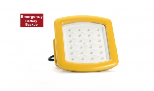
Explosion Proof Emergency Light 1.5 Hours - Class 1 Division 2 - 20W/30W/40W
Features:
CES-J40S explosion-proof light fixtures with an emergency backup battery that provides energy-efficient illumination, the emergency backup provides 1680 lumens for 1.5 hours. For normal lighting, the input voltage is AC100 - 277V, 20W, 30W, and 40W power optional.
These floodlight hazardous location LED fixtures only obtained UL844, and can use for Class 1 Div 2, Groups A, B, C, and D. For design and structure, these emergency hazardous location LED fixtures are made of die-cast aluminum, and the 8mm high tempered glass. Good heat, and 6J impact resistance.
If you need anti-corrosion performance for the marine environment, that is optional. We adapt to the electrophoresis technology and the multiple coats of marine anti-corrosion paint, all the mounting brackets and accessories are made of 316 stainless steel.
Warning:
CUL for Hazloc:
- SUITABLE FOR WET LOCATIONS;
- THIS LUMINAIRE IS ACCEPTABLE FOR OPERATION IN AMBIENT CONDITIONS NOT EXCEEDING 40°C;
- FOR SUPPLY CONNECTION, USE WIRES RATED FOR AT LEAST90°C;
- NO SERVICEABLE PARTS” OR “NO USER SERVICEABLE PARTS. DO NOT OPEN FOR CLEANING.;
- CAUTION - ″TO REDUCE THE RISK OF IGNITION OF HAZARDOUS ATMOSPHERES, DISCONNECT THE LUMINAIRE FROM THE SUPPLY CIRCUIT BEFORE OPENING. KEEP TIGHTLY CLOSED WHEN IN OPERATION.″;
- THIS PRODUCT MUST BE INSTALLED IN ACCORDANCE WITH THE APPLICABLE INSTALLATION CODE BY A PERSON FAMILIAR WITH THE CONSTRUCTION AND OPERATION OF THE PRODUCT AND THE HAZARDS INVOLVED;
- “CAUTION – RISK OF SHOCK” and “DISCONNECT POWER BEFORE SERVICING”.
UL for marine locations:
- OUTSIDE TYPE or OUTSIDE TYPE (SALT WATER);
Features
- Industry-leading efficacy: up to 130 lm/W
- -40°C to +55°C Ambient operating temperature
- Wide optics for uniform illumination
- 5 years warranty
- Entry Size: NPT 3/4”-14 ;
- Housing –Aluminum alloy (ADC12 );
- Lens – tempered glass
- Beam angle: 108°, 120°
- Dimension: 200x200x147mm
- Weight: 4kg
Parameters
- Power: 20W, 30W, 40W
- Input voltage: AC100-240/277V, 50/60Hz
- Power factor: 0.97
- Light efficacy: 120 - 140lm/W
- CCT: 3000K/4000K/5000K/5700K/6500K
- LEDs: 3030
- LED Driver: Meanwell HLG series
- Backup battery: Li-ion battery, 12W power
- Emergency: ≥90min
Certificate & Standard
Have certified CES-J fixtures with the NEC and CEC standards for hazardous location and environments
- Class I, Division 2, Groups A, B, C and D
- T-Class: T6
- Damp and wet locations
- Certificate No:E475887
- US: UL 844; UL 1598A;
- Canada: CSA C22.2 No. 137; CSA C22.2 No. 250.0;
Mounting
Versatile mounting options:
- Ceiling mount
- Drop mount
- Pole mount
- Wall Mount
- Mounting Angle:0°to ±90°;
Published in
Hazardous Locaiton LED Flood Light
Tagged under
Thursday, 24 March 2022 09:35
Lighting Requirements for Offshore Drilling Rig Platforms
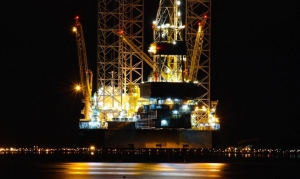
The lighting system is one of the branches of the power system of the offshore platform, which is directly related to the safety production of the platform and the quality of life of the staff. This paper briefly introduces the selection, installation method, lighting arrangement, system power supply requirements and control of the lighting system of the offshore platform.
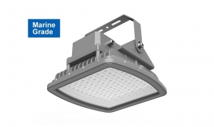
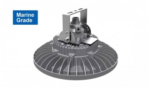
CESP LED Explosion proof Lights for Drilling Platform
Part.1 How to select lighting fixtures for offshore platform
The protection level and explosion-proof level of the lamp housing shall be suitable for the installation site and shall meet the following requirements:
The minimum requirements for the protection level of indoor dry spaces should meet IP23;
- The minimum requirements for indoor large dripping spaces and mechanical damage hazard spaces shall meet IP34;
- The minimum requirements for ballast pump rooms, refrigerated rooms, galleys and laundry rooms should meet IP44;
- The minimum protection level for outdoor and open decks should meet IP55.
- When it is in the open air or exposed to rain and waves, the minimum protection level should meet IP56.
Positive pressure ventilation (Exp), flameproof (Ex d) and intrinsically safe (Ex "ia" or "ib") are available in Class 1 hazardous areas. Increased safety (Ex e), positive pressure ventilation (Exp), flameproof (Ex d) and intrinsically safe (Ex "ia" or "ib") are available in Class 2 hazardous areas.
Some marine lighting fixtures and explosion proof lights from CESP for you reference. or you can send the project requirement to us directly.
Part. 2 The type of lighting fixtures and installation
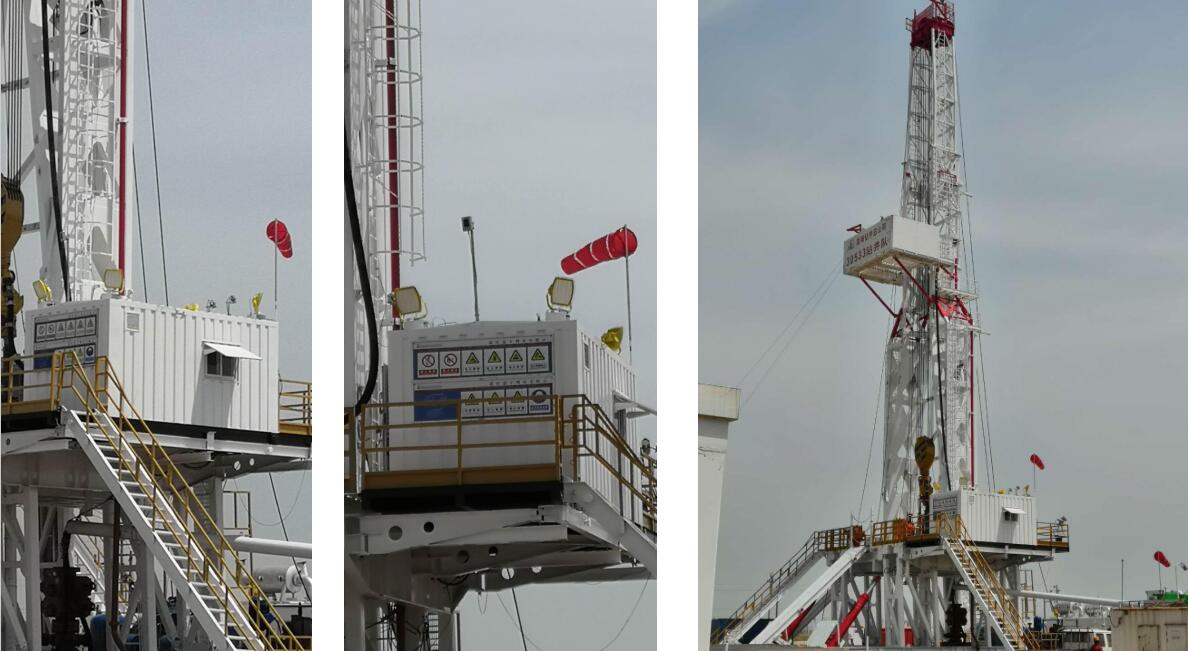
The types of lighting fixtures for offshore platforms can be divided into: fluorescent lamps, high pressure sodium lamps, metal halide lamps, emergency exit lamps, aircraft deck boundary lamps, windsock lamps, etc. Each type of lamps is used in different locations. The following mainly introduces fluorescent lamps and high pressure sodium lamps. , the installation of emergency exit lights.
- Fluorescent lamps: embedded, pole-mounted, wall-mounted, ceiling-mounted, etc.; embedded spaces are used for indoor spaces with ceilings. The pole-mounted type is installed on the boundary of the platform, the wall-mounted type is installed on the firewall, and the hoisting type is installed in the indoor mechanical space.
- High pressure sodium lamp: The high pressure sodium lamp on the platform is divided into flood light and flood light. The flood light is installed on the platform column with a height of 5.5~6 meters. The flood light mainly illuminates the interior of the platform. The floodlight should ensure that its movable part is within the illumination range required by the work, and the rotation is flexible and unobstructed, and the light is not obstructed. Flood lights are also installed on the border of the platform, mainly illuminating the sea surface.
- The emergency exit light is the light fixture of the emergency lighting system. Installed at the door of the room, it is used to indicate the escape route and indicate the rapid evacuation of personnel.
Part.3 Illumination requirements for lighting fixtures
The number and location of lamps in each area depends on the average illuminance of the room. Different areas and rooms have different illuminance requirements. The average illuminance of each area on the platform is as follows:
|
Area |
Normal lighting (average illuminance) |
|
Staircase/passage area |
100 Lux |
|
Restrooms/toilets/changing rooms/other areas |
100 Lux |
|
material storage area |
100 Lux |
|
occupancy cabin |
150 Lux |
|
machinery spaces |
150 Lux |
|
Dining Room/Infirmary/Office/Control Room/Telegraph Room |
200 Lux |
|
kitchen |
300 Lux |
|
Frequency conversion room/electrician room/distribution room |
300 Lux |
Part.4 The layout of lighting fixtures
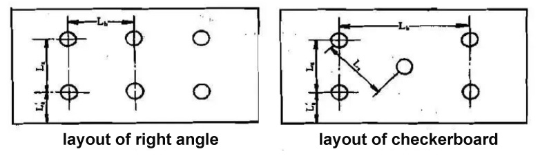
On the basis of the selected lighting fixture model, power and quantity, the cabin lighting fixtures can be arranged. While arranging, the environmental conditions of the cabin should be fully considered, and the main body should be illuminated evenly if possible. Due to the limited space in the cabin, in addition to lighting fixtures, there may be air conditioning vents, fire detectors, speakers, etc. on the ceiling. Therefore, the arrangement of lamps and lanterns must be carefully coordinated with the relevant professions. Make the lighting reasonable, beautiful and applicable as much as possible. When there is only one light in the cabin, it is generally arranged in the center, or close to the working position, and avoid placing it above the bed or in a position that may be severely blocked; when there are two or more lights in the cabin, it is In order to make the lighting of the whole room uniform, and considering the appearance of the cabin, the layout is often symmetrical. The arrangement of multiple lamps can be arranged in a right-angle or checkerboard arrangement as shown in the following figure:
The layout of other areas of the platform lighting fixtures should pay attention to the following aspects:
- It should be ensured that there is sufficient lighting in places where frequent operations and maintenance are required.
- The escape route, emergency escape and fire fighting equipment and other premises must have emergency temporary lighting.
- The arrangement and installation position and height of the lamps should ensure that the lamps are easy to operate and maintain, avoid being arranged above the movable equipment, and do not affect the aisles and safety passages, and provide lighting for the platform to the maximum extent; lamps should not be arranged in the pipeline method. To avoid the gasket breaking and the medium in the pipe spraying to the lamp.
- Emergency lighting should be arranged in the emergency equipment area so that the operation and maintenance of emergency equipment will not be affected when the emergency generator supplies power.
- The light of the lamp is not affected by any obstacles.
- The aircraft deck boundary lights and windsock lights shall ensure the safe take-off and landing of the helicopter on the offshore platform, and the arrangement and installation position shall comply with the relevant.
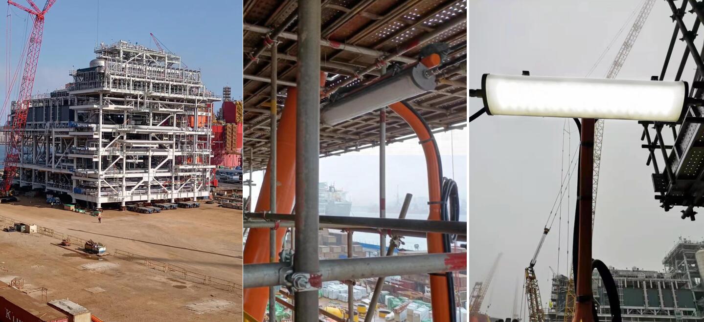
CESP Case: CNOOC - Oilfield & Offshore Lighting Engineering Project
Part.5 Lighting system power supply and control
Lighting can be divided into: normal lighting system, emergency lighting system, temporary emergency lighting system. The normal lighting switchboard shall not be placed in the same space as the emergency lighting switchboard. Except for personnel living spaces, the emergency light points in other spaces of the platform should be higher than at least 1/3 of the total number of light points in the room. Each lighting circuit shall be provided with overload and short circuit protection. Each lighting switchboard with a capacity greater than 16A should have no more than one last shunt power supply lamp.
The number of points of the last shunt-supplied lamps with a capacity less than or equal to 16A shall not exceed:
For circuits of 50V and below: 10 points
For 51~120V circuit: 14 points
For 121~250V circuit: 24 points
The power supply lamp head is close to the final shunt of the clustered cornice lighting, wall lamps, electric signs, etc. If the maximum working current does not exceed 10A, the lamp points supplied can be unlimited. The last branch of the lighting circuit should not supply power to electric heating and electrical equipment, but for small kitchen equipment (such as bread toasters, small mixers, coffee pots), small electric motors (such as desk fans, cabin fans, refrigerators) ), wardrobe heaters and the like may be excluded. For large machinery spaces, large galleys, passages (including entrances and exits), stairways leading to lifeboat decks and public spaces, the lighting is to be powered by at least two final branches for lighting. When any one of the routes is not powered, the other route should still be able to maintain the above necessary lighting.
The lighting system of the offshore platform directly affects the overall quality of the platform, so the lighting design must not only be meticulous, but also pay attention to methods, make overall arrangements, and follow specifications.
Published in
CESP Ex Wiki
Tagged under
Wednesday, 23 March 2022 06:31
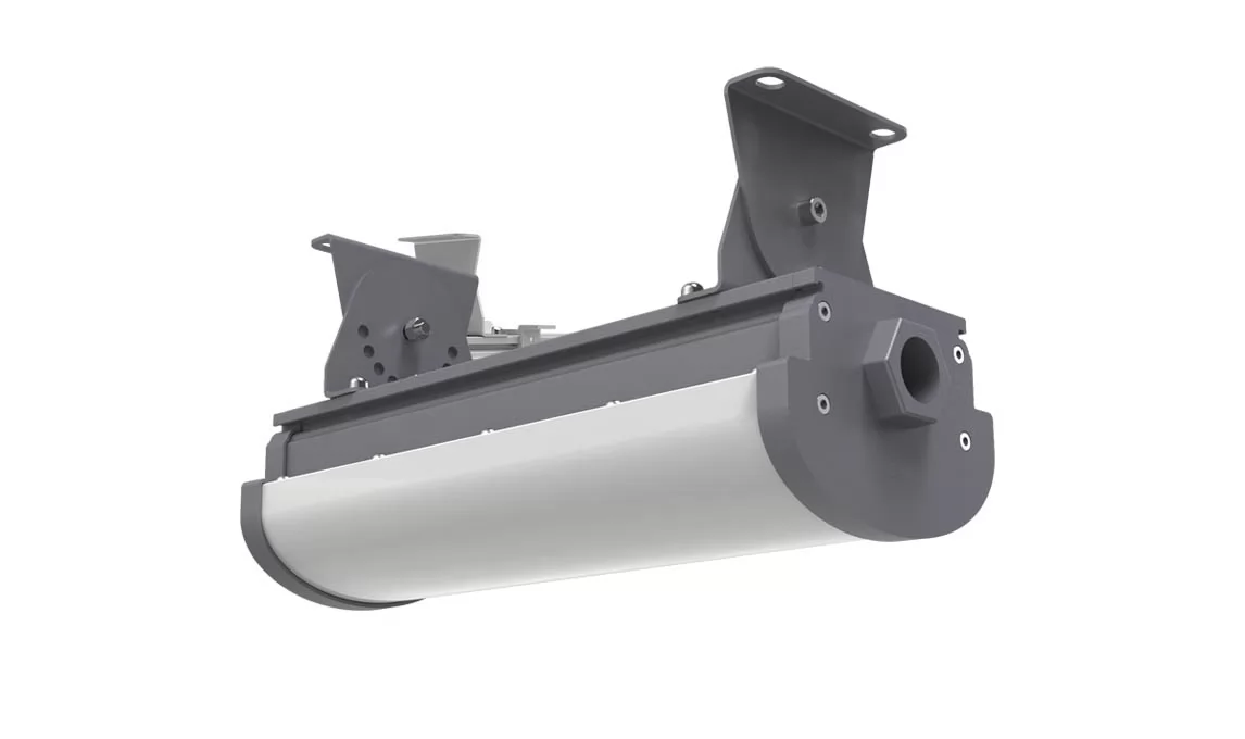
Marine Lighting - Explosion Proof Floodlight - Class 1 Division 2 - 40W to 200W
Marine Grade Explosion proof LED Flood Light | Class 1 Division 2 Light | Anti-Corrosion
In accordance with UL1598A requirements, the lamp body of CESP marine-grade LED lighting fixtures is coated with multiple layers of marine-grade anti-corrosion paint. Additionally, the mounting brackets and accessories are made of 316 stainless steel to ensure long-term reliability in harsh saltwater and atmospheric corrosion environments. Furthermore, the product includes a UL844 certification, making it suitable for Class 1 Division 2 hazardous location lighting.
Application:
• Applies to hazardous locations of Class I, Division 2 with explosive gas atmosphere.
• Applies to marine locations, non-recessed outside type (salt water).
Warning:
CUL for Hazloc:
- SUITABLE FOR WET LOCATIONS;
- THIS LUMINAIRE IS ACCEPTABLE FOR OPERATION IN AMBIENT CONDITIONS NOT EXCEEDING 40°C;
- FOR SUPPLY CONNECTION, USE WIRES RATED FOR AT LEAST90°C;
- NO SERVICEABLE PARTS” OR “NO USER SERVICEABLE PARTS. DO NOT OPEN FOR CLEANING.;
- CAUTION - ″TO REDUCE THE RISK OF IGNITION OF HAZARDOUS ATMOSPHERES, DISCONNECT THE LUMINAIRE FROM THE SUPPLY CIRCUIT BEFORE OPENING. KEEP TIGHTLY CLOSED WHEN IN OPERATION.″;
- THIS PRODUCT MUST BE INSTALLED IN ACCORDANCE WITH THE APPLICABLE INSTALLATION CODE BY A PERSON FAMILIAR WITH THE CONSTRUCTION AND OPERATION OF THE PRODUCT AND THE HAZARDS INVOLVED;
- “CAUTION – RISK OF SHOCK” and “DISCONNECT POWER BEFORE SERVICING”.
UL for marine locations:
- OUTSIDE TYPE or OUTSIDE TYPE (SALT WATER);
Features
- Industry-leading efficacy: up to 140 LM/W
- -40°C to +55°C Ambient operating temperature
- Wide optics for uniform illumination
- Fixture warranty
- Entry Size: NPT 3/4”-14 ;
- Housing –Aluminum alloy (ADC12 ) - Anti-corrosion powder coating
- Lens –tempered glass
- Beam angle: 108°, 120°
- Dimension: 300x300x165mm
- Weight: 7.5kg
Parameters
- Power: 40W / 60W/ 80W/ 100W/120W/ 150W/ 185W / 200W
- Input voltage: AC100-240/277V, 50/60Hz
- Power factor: 0.97
- Light efficacy: 110 - 140lm/W
- CCT: 3000K/4000K/5000K/5700K/6500K
- LEDs: 3030
- LED Driver: Meanwell HLG series
Ex Standard (UL844, UL1598)
Have certified CES-J fixtures with the NEC and CEC standards for hazardous location and environments
- Class I, Division 2, Groups A, B, C and D
- T-Class: T6
- Damp and wet locations
- Certificate No:E475887
- US: UL 844; UL 1598A;
- Canada: CSA C22.2 No. 137; CSA C22.2 No. 250.0;
Marine Standard (UL1598, UL1598A)
Certifications and compliancesfor marine locations:
• Damp and wet locations;
• Certification body:UL
• Certification Mark:UL
• Certificate No:E495071
Published in
Hazardous Locaiton LED Flood Light
Tagged under
Tuesday, 22 March 2022 09:39
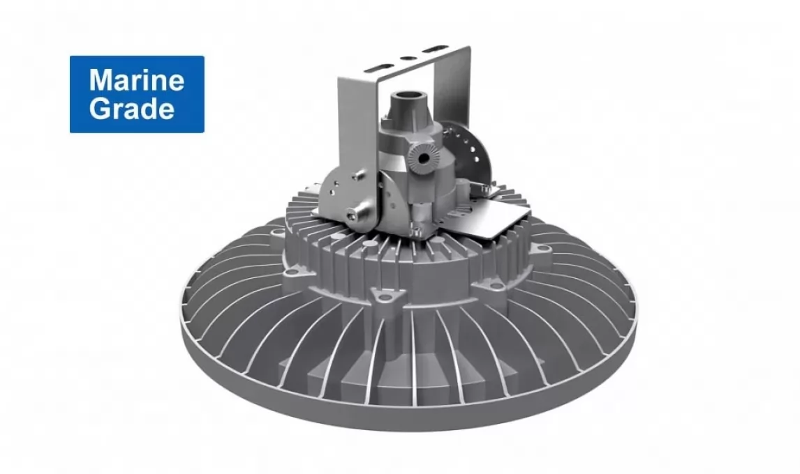
Marine Lighting - Anti-corrosion & Anti-explosive - UL1598A Listed for Marine
Marine Lighting | Corrosion Prevention | Explosion Prevention | Zone 1 Zone 21 | 100W 120W 150W 180W 200W |
CESP marine-grade lights comply with China Classification Society (CCS) standards and have obtained UL1598A marine certificate. They can be used for the most demanding exterior lighting marine environments, including sea bridges, offshore drilling platforms, ships, seaside refineries, seaside shipyards, docks, or other acid rain, seawater and salt spray corrosive environments.
Explosion-proof standard:
Applies to hazardous locations of Zone 1 and Zone2 with explosive gas atmosphere, and hazardous locations of Zone 21 and Zone22 with explosive dust atmosphere.
ATEX: EN IEC 60079-0-2018; EN 60079-1-2014; EN 60079-28-2015; EN 60079-31-2014;
IECEx: IEC 60079-0-2017; IEC 60079-1-2014; IEC 60079-28-2015; IEC 60079-31-2013;
IECEx & ATEX :
- “CAUTION-USEFASTENER WITH YIELD STRESS ≥ 640 MPa”;
- “WARNING – DO NOT OPEN WHEN ENERGIZED”;
- “WARNING – DO NOT OPEN WHEN AN EXPLOSIVE ATMOSPHERE IS PRESENT”;
- “WARNING – ONLY USE CABLES SUITABLE FOR 85°C”;
- " WARNING - DETAILED TEMPERATURE CLASS - SEE INSTRUCTIONS”;
- “THE FLAMPROOF JOINTS ARE NOT INTENDED TO BE REPAIRED”;
- End user shall use certified cable gland or conduit with suitable type of protection for final installation purpose;
- External earthing wire shall be connected when used and the cross-sectional areashall be more than 4mm2 or 10AWG;
- Under rating condition, maximum temperature on the luminaire’s shell shall not be higher than 130℃ for T4.Temperature at cable inlet shall not be higher than allowable limit of the cable applied, to ensure the cable operation normally. The branch point is 83.6℃ and cable entry point is 69.4℃
Features
- Industry-leading efficacy: up to 130lm/W±5
- -40°C to +45°C /50°C /55°CAmbient operating temperature
- Mounting: U-bracket
- Wide optics for uniform illumination
- 5 years warranty
- Entry Size: M25Χ1.5 or NPT 3/4”-14
- Housing –Aluminum alloy (ADC12 ) +Anti-corrosion powder coating
- Lens – tempered glass (10mm)
- Beam angle: 120°
Parameters
- Power: 100W / 120W / 150W/ 180W / 200W
- Input voltage: AC100-240/277V, 50/60Hz
- Power factor: 0.97
- Lumen flux: 13000LM / 15600LM / 19500LM / 23400LM / 26000LM
- CCT: 2700K - 6500K (Optional)
- LEDs: 3030
- LED Driver: Meanwell HLG series
- Dimension: Φ460 x 243(287)mm
- Weight: 14.3KG
Certificate & Standard
Have certified CES-EX-GB fixtures with the IECEX and ATEX standards for hazardous location and environments.
ATEX:
- II 2G Ex db op is IIC T4…T5…T6 Gb
- II 2D Ex tb op is IIIC T103°C…T98°C …T93°C Db
- Certify No:SEV 19 ATEX 0334 X
IECEx:
- Ex db op is IIC T4…T5…T6 Gb
- Ex tb op is IIIC T103°C…T98°C …T93°C Db
- Certify No:IECEx SEV 19.0040X
Published in
Explosion proof LED High Bay Light
Tagged under
Friday, 18 March 2022 05:35
AQ 1043-2007 Mining Product Safety Signs
1 Scope
This standard specifies the requirements for the classification, type, size, material, color, use and management of safety signs for mining products.
This standard applies to mining products that have been included in the management of safety signs and have obtained safety signs.
2 Terms and Definitions
The following terms and definitions apply to this standard.
2.1 Mining Products
The general term for equipment, materials, and instruments used in mines.
2.2 Mining Products Safety Label
Graphical and numerical codes for safety signs for mining products.
3 General requirements
3.1 The mining product safety sign management system is a mandatory management system for mining products involving workplace safety and worker health. All mining products included in the safety sign management can only be obtained after obtaining the mining product safety sign. production, sale and use.
3.2 The safety mark of mining products is a certificate that confirms that the mining products conform to national standards and industry standards, that production units are permitted to produce and sell, and that users purchase and use them.
3.3 The mining product safety sign consists of two parts: the mining product safety sign certificate and the mining product safety sign.
3.4 Mining product safety signs and logos (hereinafter referred to as "logos") are special signs that indicate that mining products comply with national standards, industry standards and relevant regulations on mine safety production.
For the production of mining products that are included in the management of safety signs, the signs can only be used after obtaining the safety signs of mining products.
3.5 Products that have obtained safety signs for mining products can only be sold by the production unit after the label is applied, and purchased and used by the user unit.
4 Identification Types
The identification is divided into safety signs for coal mine products and safety signs for metal and non-metal mine products, and there are standard and non-standard types.
4.1 Coal mine product safety signs
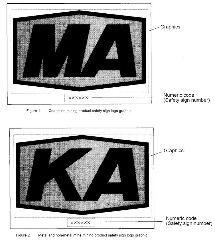
The standard identification is a hexagonal frame with the Chinese Pinyin abbreviation "MA", which means "coal safety". The frame line indicates that the scope of coal mines in the country is applicable, and the digital code is the safety sign number, as shown in Figure 1.
4.2 Safety signs for metal and non-metal mine products
The standard identification is a hexagonal frame with the Chinese Pinyin abbreviation "KA", meaning "mine safety", the frame line indicates the scope of the national metal and non-metallic mines, and the digital code is the safety sign number, as shown in Figure 2.
5 Identification graphics and parameters
5.1 Standard identification
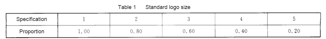
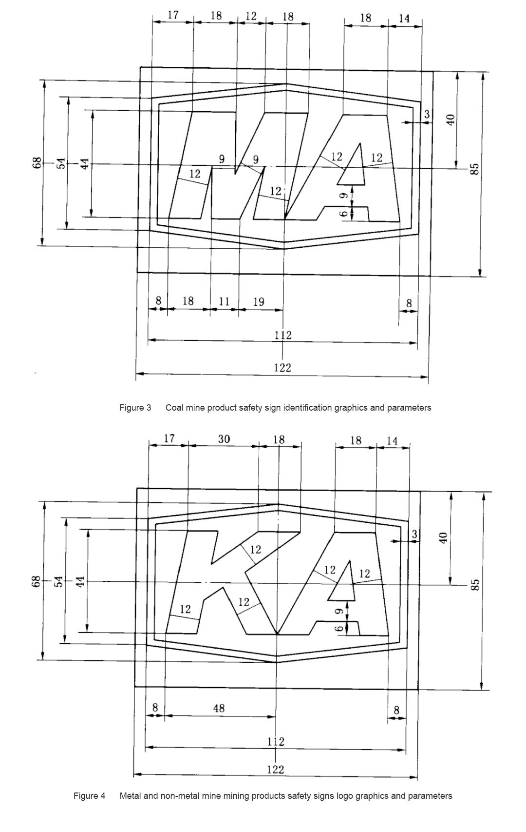
5.1.1 The standard logo graphics and parameters are shown in Figure 3 and Figure 4.
5.1.2 There are five specifications for the standard type identification, and the ratio of each specification size to the marked size in Figure 3 or Figure 4 is shown in Table 1.
5.1.3 The digital code (safety sign number) is marked below the hexagonal frame, at the center of the sign.
5.1.4 The standard logo is a yellow base plate, and the frame and "MA" and "KA" are black.
5.2 Non-standard identification
When it is inconvenient to use standard logos, non-standard logos can be applied to products by means of printing, molding, branding, etc. The position of the digital code, graphic size, color and whether to use a hexagonal frame can be determined according to specific circumstances.
6 Identify other requirements
6.1 Marking material
Standard signs should be made of materials permitted by mine safety, generally brass or stainless steel.
6.2 Identifying the surface quality
The identification should be clear and free of burrs.
7 Use of the logo
7.1 The logo should be applied to the obvious position of the outer body of the product, and the selected specifications should be compatible with the overall dimensions of the product.
7.2 For cables, conveyor belts, pipes, air ducts (cloth) and other products, the distance between the markings shall not be greater than 10 m, and there shall be no less than one marking in the minimum use unit of the product.
7.3 If the logo cannot be applied on the product body, the logo should be applied on the smallest package of the product.
7.4 Mining products that have obtained safety signs shall be marked before leaving the factory; imported mining products that have obtained safety signs in batches shall be marked before the products are delivered for use.
8 Management of logos
8.1 The labels shall be uniformly managed by the state-authorized mining product safety label review and issuance agencies.
8.2 For non-standard signs, the production unit that has obtained the safety sign shall apply to the state-authorized mining product safety sign review and issuance agency, and can only be used after confirmation and filing.
8.3 Mining products managed by Vanner Safety Signs shall not use the signs without obtaining the safety signs of mining products.
Published in
CESP Ex Wiki
Tagged under
Tuesday, 15 March 2022 06:07
Zone 1 Explosion Proof LED Work Light - 360 Beam Angle - 30W - IECEx ATEX
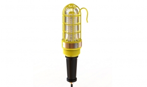
This explosion proof work light is Ex d type, 30 watt can replace to the traditional fluorescent lamps, 360 beam angle of optics design, rated for Zone 1&21, Zone 2 &22, and it's ideal for general work activities in hazardous location requiring explosion proof protection. In addition, this hand light’s lighting effects are particular good in the horizontal and vertical plane, no glare, no flicker, to improve the safety of the working at night.
Structure & Material
Patent structure design, explosion proof aluminum alloy, good heat dissipation.IP65 protection rated, lasting and reliable.
Glass: Tempered, 78% Transmittance, shock & vibration resistant.
Power Driver: Meanwell HLG Series, 90% driver efficacy.
Light efficacy up to 90lm/W. Optimize illumination in vertical plane.
No glare to ensure a comfortable.
Up to 80% energy save renovation solution.
Parameters
Power: 30WVoltage: 100-277V, 50-60 Hz
Power Factor: >0.95 @277V
THD: <15%
Operating Temperature: -40℃<Ta<50℃
Color Temperature: 2700-6500K
Luminous Flux: 3600lm
CRI: >73
Luminous Efficacy: 120±5 lm/W
Luminous Efficacy: 120±5 lm/W
Published in
Explosion proof LED Hand Lamp
Tagged under